
The Eupalinus Tunnel (Tunnel of Samos) was part of the ancient city of Samo’s aqueduct. The tunnel was built in the mid-6th century B.C. and has been referred to as one of the most significant technical achievement of antiquity. The tunnel was described by Herodotus the “amphistomon orygma” (double-mouthed tunnel) because of it’s two openings. Project engineer for the tunnel was Eupalinus. The tunnel was in use for at least 1,100 years and was abandoned when clay pipes became completely clogged allowing no water flow.
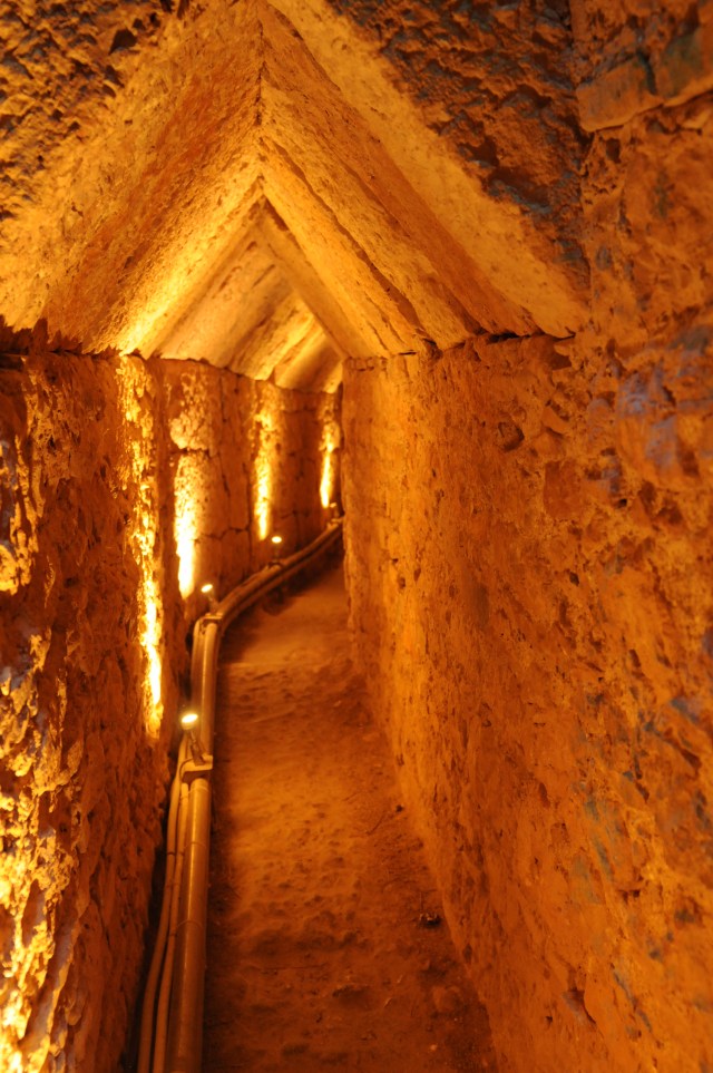
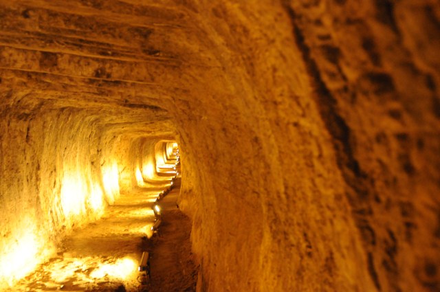
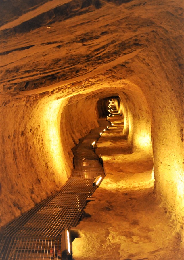
The tunnel was excavated, using hammers and chisels, through the limestone simultaneously from both the north and south sides and intersected in a fairly straight line. Time to excavate this tunnel has been estimated in the range of 8 to 10 years (ca. 550 B.C.) The tunnel is the central section of the Eupalinos Aqueduct having a length of 1,036 meters. The overall scheme of the tunnel was the large tunnel (interior dimensions of 1.8 x 1.8 meters) below which a shaft (ditch) with a depth that varied from 4 meters at the northern end to 8.9 m at the southern end. At the bottom of shaft is a corridor (ca. 0.60 meter wide). In the shaft the clay pipe was placed where water flowed.
Eupalinus Aqueduct
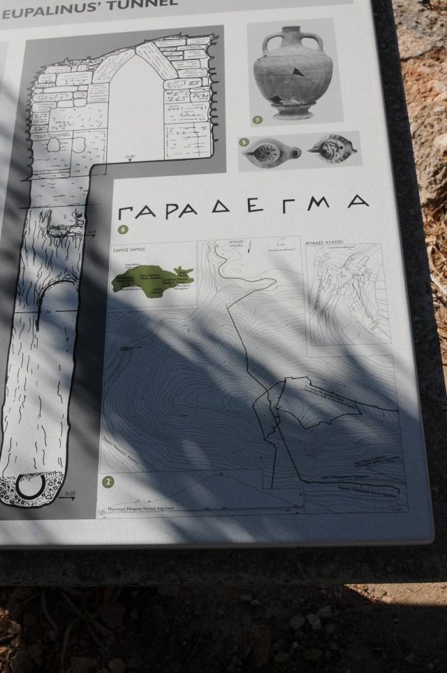
Eupalinus aqueduct started at the Ayades spring where water was collected in a rectangular reservoir covered by stone slabs. From the reservoir, water was transferred from the reservoir by an underground 890 feet long clay pipe to the northern entrance of the tunnel. Flow of around 400 cubic meters for the system has been estimated. Water from the southern exit of the tunnel flowed in an underground channel, with manholes at various intervals, to the ancient city of Samos. Reservoirs and fountains received the water.
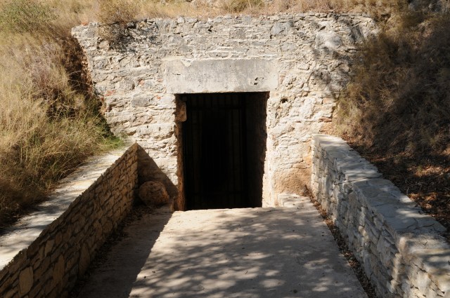


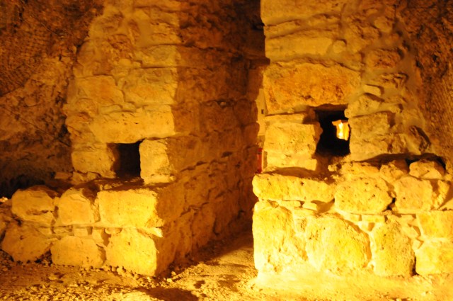
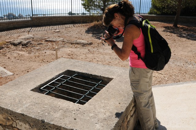
Opening to access tunnel
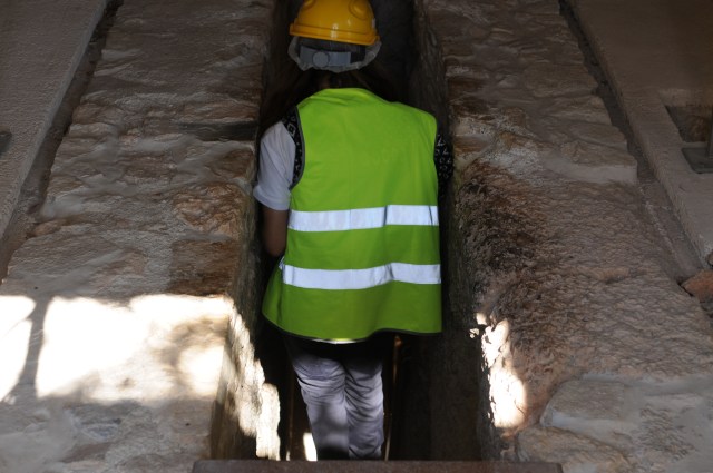
Shows modern-day metal grate over the vertical shaft.

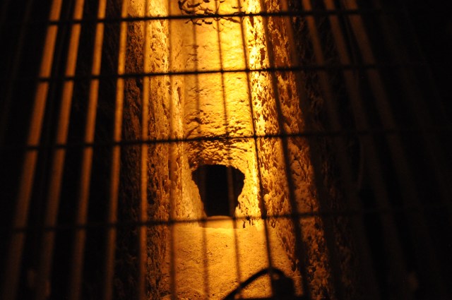
Shows vertical shaft at the bottom of which is the corridor where clay pipe was placed.
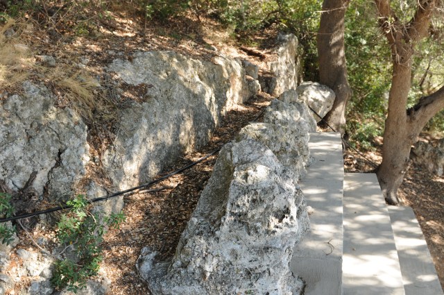

Shows the positioning of the upper part of the tunnel and the excavated section below the tunnel where the clay pipes was placed. On the right is the layout of the Eupalinus aqueduct.
Portion of Eupalinus aqueduct downstream of the tunnel.


Above two photo taken near outlet of the tunnel looking towards the modern day city.
References:
Apostol, T.M. (2004) The Tunnel of Samos, Engineering & Science, No. 1, pp. 31-40.
